 |
924Board.org
Discussion Forum of 924.org
|
| View previous topic :: View next topic |
| Author |
Message |
JasonK
Joined: 01 May 2014
Posts: 28
Location: Detroit, MI
|
 Posted: Fri May 23, 2014 4:20 am Post subject: Posted: Fri May 23, 2014 4:20 am Post subject: |
 |
|
Yes the other one is indeed BrWt and grounded which it should not be, I'm trying to figure out 1. where it goes 2. If this may fix/cause my fuel pressure to be wrong.
The YeRd is spliced FROM ReBk between T7A and the CSV injector.
Edits
The BrWt should be on Temp Sw a10 per my diagram, is that the one on the coolant tube? where does yours go?
Coolant Tube
Right now i have BlYe d33 on that sensor, where does that go? I could have an open contact hiding somewhere on the rear coolant Flange. |
|
| Back to top |
|
 |
larchie
Joined: 19 Jun 2003
Posts: 297
|
| Posted: Fri May 23, 2014 5:10 am Post subject: |
|
|
| JasonK wrote: | On a '79 the YeRe wire goes from ReBk to the Supplementary Start Valve (SSV) a10. Is this a cylinder on the side of the airbox, can someone explain this?
I don't think it's present on a '78 and I do not see the Air Flow Sensor plug (pic 3.31.7) on my air sensor unit. |
I think I wrongly thought you were working on a 1978. Is it instead a 1979 NA? If you have the solenoid at the fuel distributor, it wouldn't be a 1978 unless the PO re-fitted a later fuel distributor.
This overall diagram from Hanes might help -- different years have different wiring colors:

Fuel System Electrical Connections (1979- on) |
|
| Back to top |
|
|
JasonK
Joined: 01 May 2014
Posts: 28
Location: Detroit, MI
|
| Posted: Fri May 23, 2014 5:15 am Post subject: |
|
|
| Ok yes i see that on page 88, I'd like to know what that #2 temp switch looks like and where it is located. I do not trust my wiring.[/img] |
|
| Back to top |
|
|
larchie
Joined: 19 Jun 2003
Posts: 297
|
| Posted: Fri May 23, 2014 5:40 am Post subject: |
|
|
| JasonK wrote: | The BrWt should be on Temp Sw a10 per my diagram, is that the one on the coolant tube? where does yours go?
...
I'd like to know what that #2 temp switch looks like and where it is located. |
The 2 Temperature Switch in the diagram is in the coolant return line. So the BR/WH wire from the solenoid (supplementary start valve) terminates there as what I imagine you are seeing in your Figure 3.27 in your Hanes p. 88.
Edit: The link to the "Coolant Tube" ( https://docs.google.com/file/d/0B8bhQDrCOyeiV0lKVG40cW5jb1k/view ) doesn't have view permissions for me. |
|
| Back to top |
|
|
larchie
Joined: 19 Jun 2003
Posts: 297
|
| Posted: Fri May 23, 2014 6:43 am Post subject: |
|
|
| JasonK wrote: | | Right now i have BlYe d33 on that sensor, where does that go? |
The BL/YE wire should go from the Coolant Temperature Indicator in the Instrument Cluster through the firewall to the seven-pole connector T[sub]7a[/sub][sup]4[/sup] connector in the engine compartment to the Coolant Temperature Sender Unit in the Coolant Return Line. (Sorry, it looks like the board has a version of BB code that won't do superscripting and subscripting.)
Here's the current flow diagram for the 1979 Supplementary Start Valve:
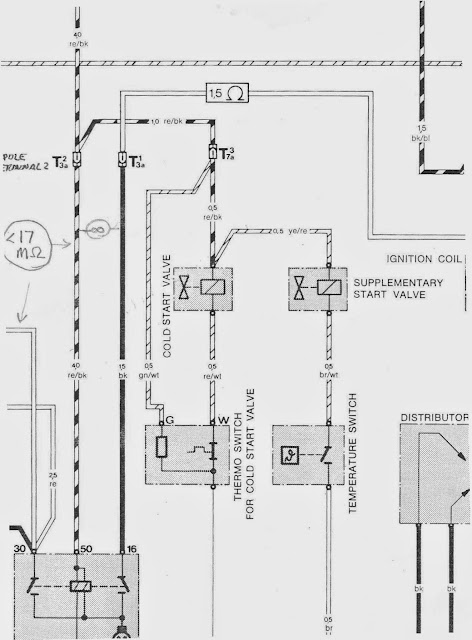
1979 Supplementary Start Valve Wiring
| JasonK wrote: | | The YeRd is spliced FROM ReBk between T7A and the CSV injector. |
So, your description would fit the above writing diagram, as best I can understand.
| JasonK wrote: | | Yes the other one is indeed BrWt and grounded which it should not be, I'm trying to figure out 1. where it goes 2. If this may fix/cause my fuel pressure to be wrong. |
The BR/WT wire is the wire to the Supplementary Start Valve's Temperature Switch. For a picture, review left-most switch in Fig. 2 and 3 in previous post, previous page. So if the BR/WT wire does not go to the temperature switch extra control fuel pressure will not be produced when needed for starting when the engine is hot. Once the car is running, however, the fuel pressure should return to normal. So the only effect I can see on performance would be on the occasion of a hot-start situation.
There are tests for the solenoid in the Hanes manual, if it is defective. Here, my guess is that if defective, the solenoid would not be triggered so the return fuel line would not be restricted and consequently there would be no change in running performance -- again the only deleterious consequence would be a more difficult hot-start. |
|
| Back to top |
|
|
JasonK
Joined: 01 May 2014
Posts: 28
Location: Detroit, MI
|
| Posted: Fri May 23, 2014 7:33 am Post subject: |
|
|
Great I think we found a problem, thats progress :)
what is on there right now is a BlYe (Blue /Yellow), so now I need to identify where that goes. It is suppose to be on the Coolant Temp Sender Unit, sec2.5 pg65 sais "the rear coolant flange... houses the coolent temperature sensor as well as the thermo time sw..."
Is this "Coolent Temperature Sensor" on pg65 the same component as the "Coolant Temperature Sender Unit" on pg260?
I guess i should remove that and I may find what I'm looking for.
Ps. I will find a better way to post pictures from my phone asap. |
|
| Back to top |
|
|
larchie
Joined: 19 Jun 2003
Posts: 297
|
| Posted: Fri May 23, 2014 8:56 am Post subject: |
|
|
My Hanes Manual pages don't match yours but yes, the Coolant Temperature Sensor is a different name for the Coolant Temperature Sender. Here's an image which might help to view where the Coolant Temperature Sensor is located under the distributor at the back of the engine:
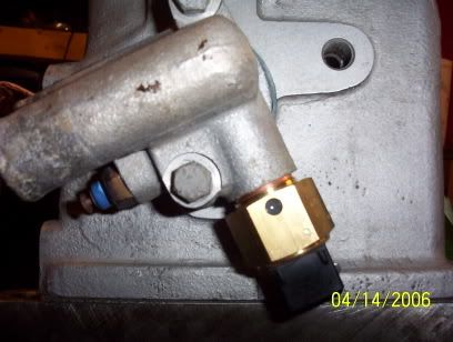
Coolant Flange with blue Temperature Sensor -- BL/YE wire disconnected (credit Adismo)
I not sure which problem you are solving now. Are you having difficulty starting the car because of fuel pressure or are you just checking the wiring because of the multiple lead plug near the distributor is missing? |
|
| Back to top |
|
|
JasonK
Joined: 01 May 2014
Posts: 28
Location: Detroit, MI
|
| Posted: Fri May 23, 2014 9:11 pm Post subject: |
|
|
Yes, the wiring was an obvious redflag. It barely starts, sputters then dies within a minute. I was hoping a wiring issue would fix the fuel pressure.
It's always around 75, i think I need to look at the CPR again. mike's garage under "Control Pressure to High when Cold" suggests opening it up and clearing the lines, I did not do that yet. I will try tomorrow.
Edit
While I'm back there again I think I'll remove that flange, is there a flat round Oil Pres Sender missing in that pic?
Ps. I was just reading your "leadfoot" link and it was on point about the SSV/HSV, thanks! We have some great resources here when everything is linked! |
|
| Back to top |
|
|
larchie
Joined: 19 Jun 2003
Posts: 297
|
| Posted: Fri May 23, 2014 11:16 pm Post subject: |
|
|
The quickest diagnosis would likely be to look at your fuel pump output from the fuel return line as outlined in Hanes Ch. 3 Sec. 7 -- and then the data results from the fuel pressure tests done with the Bosch pressure-test-gauge setup (or equivalent).
If you haven't done these tests already, in addition to Mike Gabriel's Rabbit fuel-pressure tips you cite and the Hanes outline, ideola has some good procedural tips in his thread How to connect & operate the Hoffman CIS Test Kit in the How-To section of the board.
You might re-title this thread or start a new one so as to get additional input from this board's K-Jetronic technical experts. |
|
| Back to top |
|
|
JasonK
Joined: 01 May 2014
Posts: 28
Location: Detroit, MI
|
| Posted: Mon Jun 02, 2014 3:08 am Post subject: |
|
|
Thanks Larchie, yes I appreciate the suggestions... your link was also the first link on my first post. Right now I'm still having the same problem (High Control Pressure). Maybe I will start a new post rather than rename this thread, however I'll recap what I have done so far here too.
Dropped and cleaned fuel tank.
Tested flow-rate on both fuel pumps ~10s w/engine off
Tested flow-rate after fuel filter ~15s w/engine off
Tested flow-rate on return line ~20s w/engine off
Assuming return line is not clogged *
System Pressure 75-80, good
Maybe I'm doing something wrong while testing the control pressure? I will try to document all of my interpretations / assumptions here... hopefully something is silly/wrong.
Testing with engine off,
unplugging both Aux Air (AAV) and Control Pressure Regulator (CPR).
expecting a cold control pressure of about 22psi, observing 75.
Otherwise I must have two bad CPR. I rebuilt one CPR already... blew out both pinholes with compressed air and it did not fix the problem.
Fuel Pressure Regulator (on Fuel Distributor) seems to be working correctly. I'm not sure I understand 100% how the two work together, and I definitely do not understand why the CPR was mounted on the back of the engine. I am fairly certain I have isolated the problem to the CPR however, and I am fairly certain I do understand how it is suppose to work.
I have blown air through both lines to and from the CPR. Since they have different diameter banjo bolts it is not possible for them to be switched... I guess my next step is to disassemble the working vehicle and test with that (a third) CPR, which I was really hoping not to have to do.
Right now I'm done for this week... next weekend I'll try again to solve this mystery. I am quite determined to get this car running. Appreciate any specific ideas /hints.
Best,
* Assuming return line is not clogged... because bypassing does not fix problem when flowing into a container the control pressure is still 75psi. |
|
| Back to top |
|
|
larchie
Joined: 19 Jun 2003
Posts: 297
|
| Posted: Mon Jun 02, 2014 7:00 am Post subject: |
|
|
| JasonK wrote: | | Fuel Pressure Regulator (on Fuel Distributor) seems to be working correctly. I'm not sure I understand 100% how the two work together, and I definitely do not understand why the CPR was mounted on the back of the engine. I am fairly certain I have isolated the problem to the CPR however, and I am fairly certain I do understand how it is suppose to work. |
Figure 1 below shows the relation of the control pressure regulator to the fuel distributor. If the pressure on the top of the control pressure regulator's (i.e., WUR's) diaphragm increases because of the wider metering port openings in the fuel distributor, the WUR's diaphragm is pressed down causing more fuel to flow to the injectors as in Figure 2.
When the flow to the injectors increases, the increased pressure from the fuel distributor is relieved somewhat, and the pressure in the system is maintained at a constant level. The WUR then allows increases or decreases in the amount of fuel delivered to the injectors so as to keep the fuel pressure to the injectors constant.
The coil spring in the WUR exerts pressure on the diaphragm working in opposition to the fuel pressure. When the engine is cold, the flat thermostatic spring and the fuel pressure compresses the coil spring which increases the amount of fuel flowing to the injectors in order to prevent a too lean fuel mixture when starting.

Fig. 1: Schematic of Control Pressure Regulator (WUR) and Associated Components
(Note the heating element wound around the thermostatic spring of the warm-up regulator.)
| JasonK wrote: | | ... and I definitely do not understand why the CPR was mounted on the back of the engine. |
The WUR responds to the heat from the engine oil and engine. The heat from the engine is necessary to deflect the thermostatic spring of the WUR reducing the compressing force on the coil spring which in turn exerts force on the diaphragm and reducing fuel flow to the injectors.
In addition to the engine heat, the thermostatic spring responds to an electrical heating element which prevent the fuel pressure from remaining high for too long in cold weather.
And a slightly different schematic diagram:
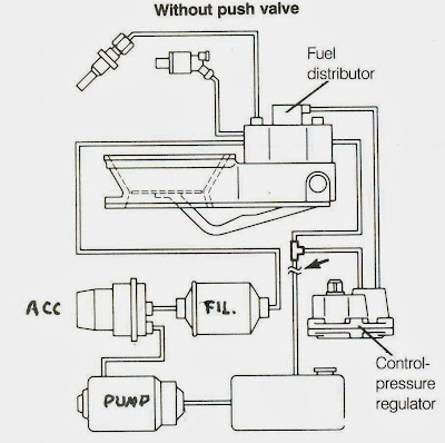
Fig. 2: Schematic of Fuel System (Arrow marks test point of fuel-pump delivery)
| JasonK wrote: | | I have blown air through both lines to and from the CPR. Since they have different diameter banjo bolts it is not possible for them to be switched... I guess my next step is to disassemble the working vehicle and test with that (a third) CPR, which I was really hoping not to have to do. |
Two things worth trying before more expense:(1) Clean the screens of the WUR. Recently both jdub and ThomasJoseph315 have had good results with this.
(2) Test the heating element of the WUR with an ohmmeter across the contacts. If the heating elemint is infinite ohms or not between about 16 and 22 ohms, then the WUR is faulty. I haven't taken time yet to study carefully your data -- if I find anything of interest I post later. Thanks for posting the numerical values -- it should help to find out what's going on. |
|
| Back to top |
|
|
Rasta Monsta

Joined: 12 Jul 2006
Posts: 11733
Location: PacNW
|
| Posted: Mon Jun 02, 2014 2:42 pm Post subject: |
|
|
| larchie wrote: | If the pressure on the top of the control pressure regulator's (i.e., WUR's) diaphragm increases because of the wider metering port openings in the fuel distributor, the WUR's diaphragm is pressed down causing more fuel to flow to the injectors as in Figure 2.
When the flow to the injectors increases, the increased pressure from the fuel distributor is relieved somewhat, and the pressure in the system is maintained at a constant level. The WUR then allows increases or decreases in the amount of fuel delivered to the injectors so as to keep the fuel pressure to the injectors constant. |
There is literally nothing correct about any of this.
_________________
Toofah King Bad
- WeiBe (1987 924S 2.5t) - 931 S3
|
|
| Back to top |
|
|
larchie
Joined: 19 Jun 2003
Posts: 297
|
| Posted: Mon Jun 02, 2014 5:44 pm Post subject: |
|
|
| Rasta Monsta wrote: | | There is literally nothing correct about any of this. |
There is nothing factually wrong in what is written. My summary was an over-simplification which, I think, is appropriate for a message board even though other aspects of the operation of the WUR are omitted. However, what is said in the post you critique is a summary of almost exactly what is said in some of the basic manuals for K-Jetronic CIS. I have selected just a few quotes to illustrate below that what is stated is factually O.K. This is the question which is being addressed in my post:
| JasonK wrote: | | Fuel Pressure Regulator (on Fuel Distributor) seems to be working correctly. I'm not sure I understand 100% how the two work together {i.e., CPR aka WUR} |
And these are the sentences under question:
Sentence 1: If the pressure on the top of the control pressure regulator's (i.e., WUR's) diaphragm increases because of the wider metering port openings in the fuel distributor, the WUR's diaphragm is pressed down causing more fuel to flow to the injectors as in Figure 2.
Webber writes in his Bosch CIS manual, "The warm-up regulator (also called the "control-pressure regulator") determines the control pressure for the system" (p. 39). Bentley discussing the control pressure regulator for CIS continues such that my summary is a close paraphrase of sentence 1: "If the pressure on the top of the control pressure regulator's diaphragm increases because of the wider metering port opening in the fuel distributor, the control pressure regulator;s diaphragm is pressed down -- thus allowing more fuel to flow to the injectors" (p. 44). Hanes writes, "The metering ports can control the supply of fuel to the injectors accurately only if the the pressure difference on either side of the port is kept constant" (p. 75).
---
Sentence 2: When the flow to the injectors increases, the increased pressure from the fuel distributor is relieved somewhat, and the pressure in the system is maintained at a constant level.
Hanes writes, "As the engine warms up the control pressure regulator valve closes and the pressure on the top of the plunger become system pressure moving the plunger down a little and returning the mixture to normal" (p. 75) Webber writes, "It {i.e., the WUR} also works in conjunction with the fuel distributor and primary pressure regulator to refine the control pressure as engine demands require" (pg. 39). The Bentley document specifies this "refinement" in very close language to my summary of that account. The Bentley sections states, "As the diaphragm's movement increases the flow to the injectors, the increased pressure from the fuel distributor is relieved, and the pressure in the system is balanced to maintain its regulated level" (p. 44). My sentence either is, or is close to being an exact paraphrase of Bentley.
---
Sentence 3: The WUR then allows increases or decreases in the amount of fuel delivered to the injectors so as to keep the fuel pressure to the injectors constant.
I'll just quote Bentley on this one: "The control pressure regulator therefore serves to permit increases or reductions in the quantity of fuel delivered to the injectors without any change in the pressure at the nozzles" (p. 44). -- which again, my statement is a fair paraphrase.
---
If you believe more explanation is necessary for other aspects of the relation between the fuel distributor and the control pressure regulator, it might have been a bit more help to solving the problems at hand to have provided that explanation.
I'm not an expert or authority on CIS or the 924 and have never claimed to be, but if as you say, "There is literally nothing correct about any of this," then, as clearly shown above, that generalized judgment would also have to apply in equal measure pari passu to the acknowledged CIS authorities quoted in this post. |
|
| Back to top |
|
|
Rasta Monsta
Joined: 12 Jul 2006
Posts: 11733
Location: PacNW
|
| Posted: Tue Jun 03, 2014 1:01 am Post subject: |
|
|
I would not call Bentley an authority on CIS. The proof is well laid out above.
Your "summary" is your interpretation of a gaggle of unrelated quotes from different sources, and is not only wildly incorrect, but smacks of someone trying to regurgitate the expertise of others in an attempt to appear expert themselves when they are not.
If the OP wants an accurate description of the system, I recommend studying THIS.
rasta
P.S. Latin on a car board? 
_________________
Toofah King Bad
- WeiBe (1987 924S 2.5t) - 931 S3
|
|
| Back to top |
|
|
larchie
Joined: 19 Jun 2003
Posts: 297
|
| Posted: Tue Jun 03, 2014 3:12 am Post subject: OT: Rasta Monsta and His Personal Attacks |
|
|
Rasta, you twice missed the specific point at issue:
| Rasta Monsta wrote: | | If the OP wants an accurate description of the system ... |
He did not. This is specifically what JasonK asked:
| JasonK wrote: | | I must have two bad CPR. I rebuilt one CPR already ... Fuel Pressure Regulator (on Fuel Distributor) seems to be working correctly. I'm not sure I understand 100% how the two work together |
And this is specifically what was summarized in my post. I get it that you denigrate the sources of my information, but that does not belie their factual accuracy.
| Rasta Monsta wrote: | | Your "summary" ... smacks of someone trying to regurgitate the expertise of others in an attempt to appear expert themselves when they are not. |
Rasta, read 5 lines above this sentence in your post to find my statement on my level of expertise which has been stated many times on this board. One fairly recent example includes this:
| larchie wrote: | | I know I have stayed with the 924 mainly because, as someone who knows very little about maintaining and repairing cars and someone who has great appreciation for the skills of dedicated and accomplished mechanics, including those on this Board, it's one way I can participate in learning about and acknowledging the fascinating way these machines are designed to function. So I didn't come to Porsche 924 as an enthusiast, but more as someone who respects their design and function. ... And, for me, seeing the ingenious ways these cars are maintained and rebuilt as described by the gifted and resourceful posters on this Board is fascinating. |
I was under the impression that this board welcomed people helping people and was not restricted to self-styled "experts."
P.S. The use of a phrase present in any English dictionary for a post on a "car board" seems to me to be somewhat more appropriate than the use of a post on a car board for a personal attack. |
|
| Back to top |
|
|
|
|
You cannot post new topics in this forum
You cannot reply to topics in this forum
You cannot edit your posts in this forum
You cannot delete your posts in this forum
You cannot vote in polls in this forum
|
Powered by phpBB © 2001, 2005 phpBB Group
|

