 |
924Board.org
Discussion Forum of 924.org
|
| View previous topic :: View next topic |
| Author |
Message |
Lizard

Joined: 03 Nov 2002
Posts: 9364
Location: Abbotsford BC. Canada
|
 Posted: Mon Jan 16, 2012 4:45 pm Post subject: Posted: Mon Jan 16, 2012 4:45 pm Post subject: |
 |
|
Weasel,
I have read many things on the DC unit. Most arent that good. CSR is what I would use and just run it at full with an external thermostat (if street car). I have a good BMW unit that is perfect for this.
PM for more info (I dont check in here often)
_________________
3 928s, |
|
| Back to top |
|
 |
Euro924S2

Joined: 06 Mar 2008
Posts: 215
Location: UK
|
| Posted: Tue Jan 24, 2012 6:48 am Post subject: |
|
|
Reading with interest also as I, like Carrera RSR will be fitting a newly rebuild 931 engine soon also.
To be honest I thought I had my plan settled on already but I'm keen to hear of other options before I fabricate it.
Personnaly I worry (maybe needlessly) about the catastophic failure if an electric pump failed. Also, those pumps are pretty expensive and if I reversed the flow then my heater would require some clever re-plumbing and would again be a restriction to flow.
Since I want to keep my car a practical as possible, any solution I use must atleast maintain the current heater performance, and preferably improve it.
I've discussed my plans on here before but my plan was to keep stock pump and direction. Then fabricate a new outlet flange for the rear of the head with an outlet pipe ported to outlet of the head (cant remember exact size but about 28mm IIRC). This larger diameter pipe runs all the way to the front where the funny rubber reducer hose is trimmed to accept the larger pipe into the pump. This front to back pipe however has a 3-way 'Y' splitter in it. 1 input comes from back of head, one output continues as the front to back pipe and the 3rd connection goes to the heater matrix. The heater return pipe rejoins the front to back pipe via another 'Y' splitter nearer the pump. (So far basically the same as the OEM setup but with larger pipe.) The main difference comes when I'll add two control valves. One in the heater matrix circuit, and one in the front to back pipe BETWEEN the 2 'Y' pieces. Like
(sorry can't upload proper diagram, ignore the ... they just keep the layout)
............................> OEM valve > Matrix >
HEAD > PIPE > Y ...................................... > Y > Pipe > OEM water pump
............................> 28mm valve -------->
The 2 valves are controlled via the same heater controls but so that as the OEM heater valve is opened the large diameter 28mm valve is partially closed. (Can be tweeked in car with the slider to maximise heater temp but with the minimum diverted water flow for given ambient air temp coming through the blower)
My hope is that during normal operation with heater on cold, the maximum flow of coolant (limited by the head appature) will exit the rear of the head. Then if the heater control is moved into the Hot position, some/ most of the flow is diverted towards the heater matrix. Even though this flow will be less efficient, I'm thinking the extra cooling of the heater matrix, coupled with the persistent flow of some coolant directly back to the pump will still be superior to whats there - agreed its not the 'ultimate setup' but should certainly be an improvement, without any significant drawbacks.
I hope that makes things clear - if a picture says a thousand words then my Iphone renders me mute!!!!
As always, your thoughts are welcomed!!!
_________________
UK spec '83 N/A with 931 motor with Eaton MP62 'charger @ 15psi. EFI - 565cc inj. Standalone Adaptronic ECU. 951 FMIC. Ally rad. Twin throttle. Recirc valve. Custom manifolds and CAI. 232bhp
Last edited by Euro924S2 on Tue Jan 24, 2012 7:05 am; edited 2 times in total |
|
| Back to top |
|
|
Euro924S2
Joined: 06 Mar 2008
Posts: 215
Location: UK
|
| Posted: Tue Jan 24, 2012 6:56 am Post subject: |
|
|
Oh, one more thing. When I turned my new crank pulley from billet aluiminium to drive my 6 Rib supercharger belt - I made the 'V' belt the same 140mm diameter (can't remember standar but more like 110mm IIRC). This has the effect of overspinning the waterpump and alternator and whilst I can't be sure if it's the new all aluminium radiator (smaller as it's from a Honda Civic Type-R) or this modification - my car never moves above the 1st mark on the gauge no matter how hard I drive it on the road - with my previous NA engine and a 951 radiator it never ran less than 1/2 on the same gauge. Not very scientific I know but maybe worth a mention since increasing the flow rate has already been discussed. (that said I hope I don't throw a fin off the impeller with this new RPM range!!)
Ps the alternator is still rubbish - but thats because I still need to re-new the ground!!!
_________________
UK spec '83 N/A with 931 motor with Eaton MP62 'charger @ 15psi. EFI - 565cc inj. Standalone Adaptronic ECU. 951 FMIC. Ally rad. Twin throttle. Recirc valve. Custom manifolds and CAI. 232bhp |
|
| Back to top |
|
|
Euro924S2
Joined: 06 Mar 2008
Posts: 215
Location: UK
|
| Posted: Tue Jan 24, 2012 7:11 am Post subject: |
|
|
Yet another idea, then I promise to let someone else have a say!! 
Thinking about the electric water pump used on a 944 turbo that normally supplies water to the turbo for cooling.
If this was plumbed in line in the pipe that runs front to back and either run continuously, or via a simple temp switch, or via your ECU if desired, then would this 'scavenge' a greater flow through the back of the head and increase the #4 cooling flow, rather than coolant taking the current path of least resistance via the front of the head? I'm not aware of the pluming on a 951 - is this pump ok to pump 100+ deg C water or does it only pump cooled - post radiator - water in the 951??
I'll be quiet now I promise!!
_________________
UK spec '83 N/A with 931 motor with Eaton MP62 'charger @ 15psi. EFI - 565cc inj. Standalone Adaptronic ECU. 951 FMIC. Ally rad. Twin throttle. Recirc valve. Custom manifolds and CAI. 232bhp |
|
| Back to top |
|
|
WEASEL149

Joined: 19 Aug 2005
Posts: 595
Location: UK, Sheffield
|
| Posted: Tue Jan 24, 2012 9:00 am Post subject: |
|
|
| Euro924S2 wrote: | Yet another idea, then I promise to let someone else have a say!!
Thinking about the electric water pump used on a 944 turbo that normally supplies water to the turbo for cooling.
If this was plumbed in line in the pipe that runs front to back and either run continuously, or via a simple temp switch, or via your ECU if desired, then would this 'scavenge' a greater flow through the back of the head and increase the #4 cooling flow, rather than coolant taking the current path of least resistance via the front of the head? I'm not aware of the pluming on a 951 - is this pump ok to pump 100+ deg C water or does it only pump cooled - post radiator - water in the 951??
I'll be quiet now I promise!! |
It's an interesting solution, but not being an expert on these things, I have no idea if it would work.
Your previous solution, keeping the standard pump and circuit is similar to what I did to mine.
The water exits the head at the rear through a larger pipe which runs right to the front (same route as old metal y crossover pipe).
The heater is on it's own loop T'ed off from this larger pipe then returning to the same pipe but still controlled through the heater valve. At least this way, there is always flow from the rear of the head regardless of position of heater control valve.
I didn't do much mileage with this set-up before pulling it apart but once the air was bled from the system, I can confirm that the heater was still functioning with hot air.
My engine never came close to overheating in any configuration and I have no data to prove whether this helps the cooling of the no.4 cylinder, but it must help.
As John H said, his Carrera GT replica has raced for years with no head gasket failures - this could be because he bypassed the heater, getting rid of any flow restriction. Then again, it could just be because his car has always been really well-sorted and tuned/maintained properly.
I remember talking to the guru at Strasse Porsche in Leeds about their Carrera GT racecar (I think his name is Dave Sutherland). They had gone through quite a few headgaskets racing that car. I can't help but think that this problem with 4 is the root cause of at least 50% of headgasket failures.
_________________
1979 UK 932 |
|
| Back to top |
|
|
Carrera RSR

Joined: 08 Jan 2010
Posts: 2312
Location: Somerset, UK
|
| Posted: Wed Jan 25, 2012 6:29 am Post subject: |
|
|
As my car is a toy, hardly driven in cold or poor weather I am seriously contemplating bypassing the heater matrix on the rebuild and increasing the return pipe diameter, maybe ditching the 'y' pipe altogether as it appears to restrict flow rather than speed it up. Again no expert on these matters
_________________
1980 931 - forged pistons, Piper cam, K27/26 3257 6.10 hybrid turbo, 951 FMIC, custom intake, Mittelmotor dizzy & cam pulley, H&S exhaust, GAZ Gold, Fuch'ed, Quaife
Now www.924board.org/viewtopic.php?t=34690
Then www.924board.org/viewtopic.php?t=31252 |
|
| Back to top |
|
|
Cedric

Joined: 27 Aug 2004
Posts: 2805
Location: Sweden
|
| Posted: Wed Jan 25, 2012 4:16 pm Post subject: |
|
|
| Carrera RSR wrote: | | As my car is a toy, hardly driven in cold or poor weather I am seriously contemplating bypassing the heater matrix on the rebuild and increasing the return pipe diameter, maybe ditching the 'y' pipe altogether as it appears to restrict flow rather than speed it up. Again no expert on these matters |
In a rainy country i would not do that, the mist inside the car can be really bad, even with the heater.
_________________
1980 924 Turbo
www.instagram.com/garagecedric/ |
|
| Back to top |
|
|
Carrera RSR
Joined: 08 Jan 2010
Posts: 2312
Location: Somerset, UK
|
| Posted: Thu Jan 26, 2012 4:10 am Post subject: |
|
|
| Cédric wrote: | | Carrera RSR wrote: | | As my car is a toy, hardly driven in cold or poor weather I am seriously contemplating bypassing the heater matrix on the rebuild and increasing the return pipe diameter, maybe ditching the 'y' pipe altogether as it appears to restrict flow rather than speed it up. Again no expert on these matters |
In a rainy country i would not do that, the mist inside the car can be really bad, even with the heater. |
And the heater does nothing but pump in moist warm air and compound the problem. Only way is to crack open windows.
I don't drive the car in the rain if I can help it. Been caught out two or three times in two years.
_________________
1980 931 - forged pistons, Piper cam, K27/26 3257 6.10 hybrid turbo, 951 FMIC, custom intake, Mittelmotor dizzy & cam pulley, H&S exhaust, GAZ Gold, Fuch'ed, Quaife
Now www.924board.org/viewtopic.php?t=34690
Then www.924board.org/viewtopic.php?t=31252 |
|
| Back to top |
|
|
ideola

Joined: 01 Oct 2004
Posts: 15550
Location: Spring Lake MI
|
| Posted: Wed Mar 14, 2012 1:16 pm Post subject: |
|
|
Let's not forget this option:
| bruce76-924 wrote: | Dan,
Just to put a slightley different angle on the cooling system, I run the standard pump with the bypass pipe and lower thermostat return pipe blocked off, this pushes water through the block and then out of pipe fitted instead of the rear core plug at the rear of the block. The water is then run through a second radiator and back out to a large diameter pipe ( like Steve's car ) to the back of the cylinder head, then finally exiting through the thermostat housing and back into the the first radiator.
I used to run it with 2 water pumps just to make it more complicated but I've just removed the second pump to try and simplify things a bit and the engine ran very cool when driving so I'll see what it's like with just the 1 pump.
Bruce. |
Also, for reference:
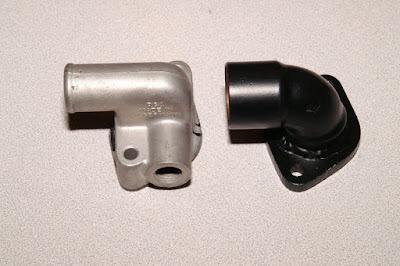
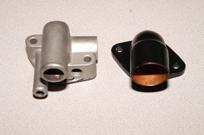
| ideola wrote: | OK, here are photos of my modified rear water flange:
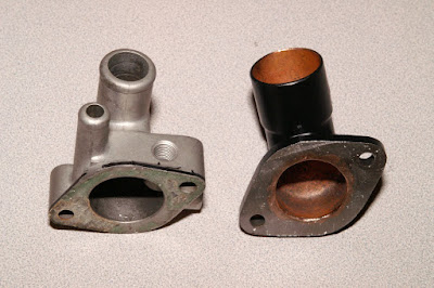 |
Now, looking at these pix, and having just noodled over this quite a lot, thinking "why am I not doing something about this on these two new motors I've just built"...
What I'm curious about in the OEM design is that the tiny diameter hole in the OEM rear water flange is what provides 100% of the flow from the head when the heater control valve is closed. What would happen if you just switched which port was used for the heater matrix??? In other words, get some standard off the shelf flexible hose and use the smaller diameter hole from the rear water flange to feed the input of the heater control valve, and get some larger diameter flexible hose to make the 90 degree turn off the big port of the water flange into the larger port on the cross over pipe? Might not be the "ultimate" solution, but it sure seems like the head would benefit from using the larger diameter circuit. Of course, cabin heating might suffer a little bit, but how many of us considering this mod are really using these as winter cars to begin with???
The benefit of using the OEM rear water flange is that you wouldn't have to worry about figuring out an alternate mounting solution for the TTS and CLT, the former being a crucial input on a CIS-equipped car. The goal of finding an alternate and improved coolant routing circuit for a road car would have to address these latter two requirements in addition to everything else, which probably not something WEASEL had to deal with, as I believe his car is EFI'd.
_________________
erstwhile owner of just about every 924 variant ever made |
|
| Back to top |
|
|
leadfoot

Joined: 11 Dec 2002
Posts: 2222
Location: gOLD cOAST Australia
|
| Posted: Wed Mar 14, 2012 6:27 pm Post subject: |
|
|
in answer to this as I did exactly that on the last car, the cooling is more efficient, and doesn't affect the heating, it still cranked the heat out,
I changed the heating circuit this time around for a solenoid valve instead of the goofy cable pull valve...
BTW adding an oil cooler will change engine temps alot more than this mod alone, helps cure heat soak at shutdown and stabilises coolant temps at running conditions,
Stu
_________________
1981 ROW 924 Turbo -
carbon fiber GT mish mash
LS1 conversion in progress... |
|
| Back to top |
|
|
ideola
Joined: 01 Oct 2004
Posts: 15550
Location: Spring Lake MI
|
| Posted: Wed Mar 14, 2012 8:53 pm Post subject: |
|
|
| leadfoot wrote: | | BTW adding an oil cooler will change engine temps alot more than this mod alone |
Can you clarify? the 931 already comes with an oil cooler...do you mean adding a larger one? adding a secondary?
Also, thanks for the confirmation on the heater hose reconfig. Why oh why didn't I do this BEFORE I dropped the motor into the club sport!!! Those buggers are a PITA to get to!
_________________
erstwhile owner of just about every 924 variant ever made |
|
| Back to top |
|
|
WEASEL149
Joined: 19 Aug 2005
Posts: 595
Location: UK, Sheffield
|
| Posted: Wed Mar 14, 2012 11:44 pm Post subject: |
|
|
I've got some photos of what i did with mine. I'll post a proper reply when i get home from work.
Mine uses the OEM rear coolant flange and is not yet converted to EFI.
I'm in agreement over fitting a large oil cooler. I do think this is an area that has been a bit overlooked as we all tend to concentrate on the water circuit.
_________________
1979 UK 932 |
|
| Back to top |
|
|
WEASEL149
Joined: 19 Aug 2005
Posts: 595
Location: UK, Sheffield
|
| Posted: Thu Mar 15, 2012 1:29 am Post subject: |
|
|
Here are the only photos I have of the coolant crossover pipe modification.
I can't just go out to the garage to take photos as I keep the car at my father's house, but I will be taking a whole lot more as the engine goes back together.
We kept the standard rear coolant flange, so this works with CIS (as it did before we pulled the engine out).
All we did with the flange was open the two waterways out more with a drill.
The standard heater pipes that go in and out of the matrix are also retained.
All we did was run a tee off the new circuit which goes to the heater, then returns as normal to the new crossover pipe.
Water flows at all times from BOTH small and large outlets on the rear coolant flange via a couple of silicon hoses that connect to the new crossover pipe.
I ran this setup on the road and can confirm that the heater worked as normal.


As you can see from the last photo, the crossover pipe has 3 inlets/connections. One from the heater and two from the rear coolant flange.
I hope this is of some help to anyone thinking of altering the circuit. This was done with the engine in the car. My father is retired so working on the cars keeps him out of trouble
 ... but he did say it was a royal PITA fabricating the copper pipe. It would be a LOT easier using silicon and various couplers/tees. ... but he did say it was a royal PITA fabricating the copper pipe. It would be a LOT easier using silicon and various couplers/tees.
In my humble opinion it's imperative to improve the coolant flow from the back of the head. We all know it's a problem on these motors.
For the record, I will be fitting the biggest oil cooler I can squeeze in 
That is, after the small issue of fitting the EFI 
_________________
1979 UK 932 |
|
| Back to top |
|
|
leadfoot
Joined: 11 Dec 2002
Posts: 2222
Location: gOLD cOAST Australia
|
| Posted: Thu Mar 15, 2012 8:44 am Post subject: |
|
|
Dan, as I did this originally on the N/A there was no oil cooler, hence the adding an oil cooler statement, although this was an automotion unit that came off a 944 challenge car and was about 2.5 / 3 times the size of the stock unit.
my config on the bypass pipe consisted of a staight pipe, same diameter as the larger outlet on the rear flange, running off a tee piece at the end, the other end of the tee was directed through a rubber elbow reducer to the heater valve in a closed loop circuit to the smaller connection on the coolant flange.
Not sure I understand fluid dynamics completely but no matter how big an entrance to a funnel is, it aint going to flow more than the exit allows,
so Weasel I think you might have been better off having a larger pipe connection from the water pump to the secondary run off to the coolant flange as it looks like the most your flow is limited by the size of the mid section of your pipe, please correct me if I'm wrong here...
Stu
_________________
1981 ROW 924 Turbo -
carbon fiber GT mish mash
LS1 conversion in progress... |
|
| Back to top |
|
|
WEASEL149
Joined: 19 Aug 2005
Posts: 595
Location: UK, Sheffield
|
| Posted: Tue Mar 20, 2012 2:05 am Post subject: |
|
|
| leadfoot wrote: | Not sure I understand fluid dynamics completely but no matter how big an entrance to a funnel is, it aint going to flow more than the exit allows,
so Weasel I think you might have been better off having a larger pipe connection from the water pump to the secondary run off to the coolant flange as it looks like the most your flow is limited by the size of the mid section of your pipe, please correct me if I'm wrong here...
Stu |
Hi Stu. I'm no expert on fluid dynamics either.
The copper pipe we used is 22mm I.D. so is actually larger than the ~20mm I.D. of the large exit on the standard coolant flange.
Both exits on the flange join to this 22mm crossover pipe - a 15mm pipe from the small exit and 22mm from the large exit.
So we essentially have a 15mm and a 22mm pipe flowing water from the rear of the head at all times regardless of the heater control valve position and flowing back to the front of the engine through a 22mm bore.
Now this may reduce to ~20mm through the 90° couplers but is still much larger than the original pipework.
I think the main thing to make sure of is that the water is flowing from the rear of the head at all times to reduce the localised heating.
Going to EFI, we may alter the rear flange anyway so it's a single 32mm exit, but I'm not sure whether or not we would gain much.
Cheers, Wes.
_________________
1979 UK 932 |
|
| Back to top |
|
|
|
|
You cannot post new topics in this forum
You cannot reply to topics in this forum
You cannot edit your posts in this forum
You cannot delete your posts in this forum
You cannot vote in polls in this forum
|
Powered by phpBB © 2001, 2005 phpBB Group
|

