 |
924Board.org
Discussion Forum of 924.org
|
| View previous topic :: View next topic |
| Author |
Message |
ESC944

Joined: 21 May 2004
Posts: 747
Location: FL
|
 Posted: Tue Jan 17, 2006 7:21 am Post subject: TURBOCHARGING 101 - DIY & THEORY Posted: Tue Jan 17, 2006 7:21 am Post subject: TURBOCHARGING 101 - DIY & THEORY |
 |
|
I was posting this in response to a recent post about aftermarket turbo kits. http://www.924board.org/viewtopic.php?t=17823
THIS WILL BE LONG AND DRAWN OUT I WILL BE ADDING MORE AND MORE...
HEADER:
1. Fabricate a log style exhaust manifold for the Turbo.
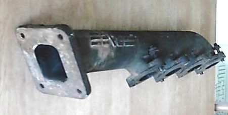
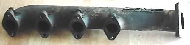
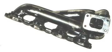
NOTE: THE WINDBLOWN manifold sucked, it was prone to cracking, but could be reinforced. THE BAE IS NOT PRONE TO CRACKS.
· The BAE manifold is an extended log manifold and places the turbo in front of the timing belt cover.
· You can also simply mount the turbo in another location more conventional. The turbo was mounted in the front for several reasons: easy of install and routing of pipes to the CIS arrangement and intake, Easy of manufacture.
· You could mount the turbo down closer to the oil pan, this creates a hanging arrangement (turbo is suspended below the header). Typical on most cars including the 924 Factory Turbo. Either Right below or a little father down.
· When mounting the turbo, you want it at a sufficient height that the oil can drain back to the oil pan.
· Make sure you have gaps in the head flange or that each runner attaches independently(BAE Style) this allows for expansion and contraction with the heat and cooling, high stress, failure to include cuts/gaps or attach independently creates areas of high stress. (prone to failure).
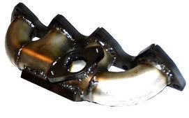
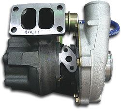
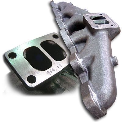
ONE OF MY BAE MANIFOLDS:

2. Fabricate an equal length arrangement, good luck with this one, there is not a lot of room to work with, but it can be done. This provides the hanging/suspended arrangement as is typical in aftermarket and stock arrangements. Other variations are possible on this type of header, the idea is it is not a log style.
Also you can or could set it up so that 2 cylinders feed one port and the other 2 feed the second port on a Turbo with a split pulse (dual port) hotside.
Collector Style
Split Port
3. Alright so there are options for the Manifold. Fabricate your own or have one made. Regardless, this is the single most critical piece in setting up a turbo on you car, without it, the turbo can not be installed, will not spin and if done poorly will suck the BIG ONE.
4. Typical cost to self fabricate (Do-it-yourself) is around 150.00 assuming you can weld, and thats for the bits, besides the exhaust flange, that flange will cost you about 100.00 to have made CNC, Water Jet, etc
assuming you have a template and can not do it yourself.
5. Having someone Else make up the whole thing, expect to pay 400.00 or so, depending on type of unit being made and who you go to.
TURBO HEADER REFERENCE
http://www.not2fast.com/turbo/em/
From My BAE Reference Files:
NON-PORSCHE:
http://www.greasecar.com/projects.cfm
http://members.aol.com/crsmp5/index/crs_cars/truck/bae_turbo/bae_turbo_kit.htm
http://www.4crawler.com/Diesel/BAEturbo/
http://www.buffalochips.org/delorean/turbo.html
Great PICS (non-porsche)
http://www.wheelspecs.com/gallery/BAEturbo12a
PORSCHE:
http://www.alexroy.net/EngineRebuild.html
http://www.alexroy.net/BAEturbo.html
http://www.alexroy.net/Intercooler.html
http://www.alexroy.net/FuelRail.html
http://www.alexroy.net/924home.html
Last edited by ESC944 on Sun Apr 09, 2006 4:14 am; edited 6 times in total |
|
| Back to top |
|
 |
ESC944
Joined: 21 May 2004
Posts: 747
Location: FL
|
| Posted: Tue Jan 17, 2006 7:24 am Post subject: |
|
|
A log style manifold design works much differently than a collector style design. A collector style manifold keeps each cylinders exhaust pulse separate until they merge at a single point called a collector. (Think 4 into 1 performance header, only smaller).
Note the Porsche 944 Turbo(951) uses a crossover pipe.
This type of arrangement can use either a log or collector style manifold and then routes the pulse under or around the engine to the other side to the turbo. A collector is better, but a log could be used (would look like a big T and would suck performance wise, but is do-able). A cross over can induce some lag, do to the distance involved, if the turbo is less than optimally selected.
There are some tricks to optimizing the exhaust pulse. To increase exhaust energy/velocity to the turbo, however I am not getting into those. Its not all about heat! I will get into Exhaust and all in my next post.
LOG MANIFOLD:
While compactness and economical manufacturing are advantages to the log style manifold design, there are multiple performance disadvantages.
Turbo response time and high rpm flow is on most engines with a collector tubular exhaust manifold design.
Lets take a look at the basic layout of a collector style manifold.
On a collector style manifold, the exhaust pulse from each cylinder travels from the cylinder head, down each manifold primary tube, and to the manifold collector. The pulses then merge and travel down the manifold secondary tube to the turbine side of the turbo. This Secondary tube, can be short or long, or in the case of a cross over arrangement, very long.
The basic idea behind keeping each exhaust pulse separate to the collector is to control and minimize the turbulence created when the exhaust pulses merge.
Uncontrolled turbulence equals lost energy, as the exhaust gas pulses lose their direction and cannot deliver their full punch to the turbine. Now of course, this effects lag, both in the onset of boost and reaching Max boost, it can also effect max boost, with regard to turbo sizing.
With a design that creates turbulence inside the manifold, energy is wasted, creating heat instead of spinning the turbine.
HEAT IS BAD< EXCESS HEAT IS NOT SOMETHING YOU WANT.
It bleeds into other things!
In a log style manifold the velocity of the individual exhaust pulse as it travels toward the turbine (turbo hot side) is disrupted by the incoming exhaust pulse from another cylinder, this hurts performance plain and simple.
All due to the turbulence created from the two pulses merging.
Any reduction of turbulence means less wasted energy!
To recap, a collector manifold style is superior to a log manifold style based on the fact that turbulence is limited to one point instead of one per cylinder after the first.
The collector has one, where all points meet in the collector and are fed to the turbine.
The log as stated has several, before even meeting the turbine. So a collector style will maximize the energy potential to the turbo. This results in faster turbo spool up, and potentially more energy to create boost.
Besides the minimization of lost energy, however, reducing turbulence also creates a freer flowing exhaust path for the engine.
Remember all engines are AIR pumps, you want to reduce the restriction in and out of the engine to maximize efficiency. |
|
| Back to top |
|
|
ESC944
Joined: 21 May 2004
Posts: 747
Location: FL
|
| Posted: Tue Jan 17, 2006 8:02 am Post subject: |
|
|
Exhaust designs seem more magic than science, more luck than proper execution. They have progressed over the years from theory, but the majority are still being scratch build, test, tried, tune all experimenting.
Only lately have computer or high end engine simulation programs been able to help in this process.
The Basics:
As the piston approaches top dead center, the spark plug fires igniting a fireball just as the piston rocks over into the power stroke.
The piston transfers the energy of the expanding gases to the crankshaft as the exhaust valve starts to open in the last part of the power stroke.
The gas pressure is still high (70 + p.s.i.) causing a rapid escape of the gases (blowdown).
A pressure wave is generated as the valve continues to open. Gases can flow at an average speed of over 350 ft/sec, but the pressure wave travels at the speed of sound (and is dependent on gas temperature).
Expanding exhaust gases rush into the port and down the primary header pipe. At the end of the pipe, the gases and waves converge at the collector. Now remember --- a log style manifold, will induce turbulence, as each wave crashes/merges into the next.
In the collector, the gases expand quickly as the waves spread out expanding into all of the available orifices including the other primary pipes. The gases and some of the wave energy flow into the collector outlet and out the tail pipe.
Ok keeping all that in mind, two basic things are at work in the exhaust system: gas particle movement and pressure wave activity. Racing has posted a lot of good stuff on intake design, wave activity, etc on the intake side. Good stuff to read.
The absolute pressure differential between the cylinder and the atmosphere determines gas particle speed. As the gases travel down the pipe and expand, the speed decreases.
The pressure waves speed is based on the speed of sound. While the wave speed also decreases as they travel down the pipe due to gas cooling, the speed will increase again as the wave is reflected back up towards the cylinder.
At all times, the speed of the wave action is much greater than the speed of the gas particles. Waves behave much differently than gas particles when a junction is encountered in the pipe. When two or more pipes come together, as in a collector for example, the waves travel into all of the available pipes - backwards as well as forwards.
Waves are also reflected back up the original pipe, but with a negative pressure.
The strength of the wave reflection is based on the area change compared to the area of the originating pipe.
This reflecting, negative pulse energy is the basis of wave action tuning. More engine tuning!! Yea so your thinking more crap to sort out, nah
most of the time someone will have done it for u, but remember when you bolt on the aftermarket exhaust, it was designed for a purpose(well supposedly it is tuned and designed for a specific power curve).
The basic idea is to time the negative wave pulse reflection to coincide with the period of overlap - this low pressure helps to pull in a fresh intake charge as the intake valve is opening and helps to remove the residual exhaust gases before the exhaust valve closes.
Typically all this is controlled by the length of the primary header pipe.
Due to the 'critical timing' aspect of this tuning technique, there may be parts of the power curve where more harm than good is done. This is one of the reasons we see people complaining about that aftermarket header SUCKING, or killing low end torque, etc
the other is Gas Speed.
Gas speed is a double edged sword as well, too much gas speed indicates that that the system may be too restrictive hurting top end power, while too little gas speed tends to make the power curve excessively 'peaky' hurting low end torque. Larger diameter pipes allow the gases to expand; this cools the gases, slowing down both the gases and the waves.
Exhaust system design is a balancing act between all of these events and their timing.
Even with compromises of exhaust pipe diameter and length, the collector outlet sizing can make or break the best design. If its piss poor then a lot of time and energy was wasted. Keep in mind I am not posting formula, talking just the concepts.
The bottom line on any exhaust system design is to create the best, most useful power curve.
All theory aside, the final judgement is how the engine likes the exhaust tuning on the dyno and on the track. TUNING, TUNING, TUNING!!
When considering a header design, the following things need to be considered:
· 1) Header primary pipe diameter (also constant size or stepped pipes?).
· 2) Primary pipe overall length.
· 3) Collector package including the number of pipes per collector and the outlet sizing.
· 4) Catalytic Converter (size, design and placement)
· 5) Megaphone/tailpipe package. (What is the muffler doing for you or not)
There are lots of ideas about header pipers and their sizing.
Typically the primary pipe sizing is related to exhaust valve and port size. But in the case of the 924 this is typically fixed (less you pop for head work, bigger valves, etc)
Header pipe length is dependent on wave tuning (or lack of it).
Wave tuning: with longer pipes you are tuning for lower rpm power and the shorter pipes favor high rpm. power.
The collector package is dependent on the number of cylinders, the engine configuration (4, 8, 6, etc. in this case we are talking inline 4), firing order and the basic design objectives (look up interference or independence).
The collector outlet size is determined by primary pipe size and exhaust cam timing. Yet another subject with regard to tuning
not talking that just yet, but the cam can be critical.
In my next post lets talk about NA vs. Turbo exhaust. |
|
| Back to top |
|
|
ESC944
Joined: 21 May 2004
Posts: 747
Location: FL
|
| Posted: Tue Jan 17, 2006 9:20 am Post subject: |
|
|
Ok so all this talk about exhaust tuning, lets look at how it applies.
N/A cars: None boosted (N/A naturally aspirated cars like the 924) utilize exhaust velocity (not backpressure) in the collector to aid in scavenging other cylinders during the blow down process.
To get the right velocity, reduce the diameter of the discharge of the collector (exhaust), which creates backpressure. Do a search on the board about backpressure and performance headers, or the net about exhaust tuning and all that.
Backpressure is an undesirable byproduct from trying to have a certain exhaust velocity. If you go too big, you lose velocity and its associated scavenging effect. Go to small and the backpressure gets ugly, more than off setting any gain made by scavenging.
YOU HAVE TO FIND THE HAPPY MEDIUM. This says nothing about exhaust tuning
For turbo cars, what this is all about
Lets toss all that mess out the window, WHAT?!!
Yea you didnt have to read all that other stuff I posted, hahaha but your so much smarter now
With a turbo header we want the exhaust velocity to be high upstream of the turbo hot side (in the header). Take a look you will see that the primaries of turbo headers are smaller diameter than those of an n/a car of about 2/3rd the horsepower.
The idea is simple, we want to get the exhaust velocity up quickly and get the turbo spooling as early as possible.
So getting the boost up early is a more effective way to torque than playing with tuned primary lengths and scavenging. The scavenging effects are small compared to what you'd get if you just got boost sooner instead. You have a turbo; you want boost. Just don't go so small on the header's primary diameter that you choke off the high end. This can also happen with the exhaust side (down pipe) of the turbo
it can choke the engine.
With a turbo that is
keep in mind a supercharger can fix a lot on a NA car, but you would get even more if the engine can both ingest and exhale well.
Downstream of the turbo hot side (from the down pipe back), you want as little backpressure as possible.
Simple, no ifs, ands, buts or what abouts, get it done, get it clear and free flowing.
"Larger is better" (to a point). The idea is to minimize the pressure downstream of the turbo hot side in order to make the most effective use of the pressure that is being generated upstream of the turbo hot side.
Remember, a turbo hot side operates via a pressure ratio. For a given turbo hot side inlet pressure, you will get the highest pressure ratio across the turbo hot side when you have the lowest possible discharge pressure.
Now to put it another way for anyone who cant wrap their head around that, you want the finned thingy in the hot side of the turbo to get pushed as hard and fast as possible, without getting choked off by a restriction.
This means the turbo hot side is able to do the most amount of work possible (i.e. drive the compressor and make boost) with the available inlet pressure.
Again, less pressure downstream of the turbo hot side is ALL GOOD. This will minimizes the time-to-boost and maximizes boost response, it will improve engine VE throughout the rev range without question.
Now a note about sizing.
Well as for 2.5" vs. 3.0", the "best" turbo exhaust depends on the amount of flow, or horsepower.
Use this as a rule of thumb, but you can allow a little variance.
¾ -1 per 100 HP is about average (over simplification) so at 250 hp, 2.5" is going to be good. Going any bigger will not get you much, if anything, but might be wickedly loud and/or get you a ticket.
300 hp and you definitely want more than 2.5, 2.75 - 3(better) would be good. If SOME HOW YOU ARE PUSHING 400-450 hp, THEN 3" IS ON THE SMALL SIDE OF THINGS.
NOW it really is more complicated than that, and there is something to be said for huge gains made by opening the exhaust up (dependent on HP level and engine configuration) from the turbo back. You also have to consider single or dual exhaust, true or cat back, x pipe, etc
As for the angle of the discharge pipe from the turbo hot side discharge, the best configuration would be a gradual increase in diameter from the turbo hot side's exducer to the desired exhaust diameter, by way of a straight conical diffuser of 7 to12 degrees included angle. This is to minimize the flow separation and friction losses.
There are lots of thoughts on internal and external wastegates and the effect of integrated exhaust discharge, its worth of discussion, but not here and now.
Necking the exhaust down to a some piss poor to small diameter is never good, but if it is necessary, then you want to do it as far downstream as possible. This is better than doing it close to the turbo hot side discharge, it will minimize the exhaust's contribution to backpressure. THE BEST: don't neck down the exhaust at all.
Also, the temperature of the exhaust coming out of a cat is higher than the inlet temperature, due to the process and compounds in the cat. So the total heat loss (and density increase) of the gases as it travels down the exhaust is not as prominent as it seems. So--- this in turn leads us to the path that mounting a rear turbo is very feasible, the primary concern would be pressurizing the extended intake pipe, but given the distance and the speed the pressurized air flows at, its hardly noticeable, but for idle and start up, a one way valve would be used to let the engine breath until positive pressure is generated in the intake pipe.
Also the extended intake pipe functions as a improvised Intercooler
you can also feed it through a finned heat exchanger, all this can in turn feed another intercooler, but given the boost levels of a NA conversion, it is hardly likely that other than the extended pipe, you would need intercooling. You just wouldnt be running enough boost.
But if you built an engine to run high boost, well then one could easily design multiple stages of cooling to generate larges amounts of delta loss(heat loss). In practice Rear mounted turbochargers are not inherently lag prone, not if sized right, keep in mind, you do not need to worry to much about down stream exhaust, since you are at the end of the exhaust most times or right after the cat, you can use conventional back pressure theory and pipe sizing to introduce significant post cat exhaust pressure and pre turbo velocity
start bigger and go smaller as you approach the turbo. Then open it up post turbo.
Another thing to keep in mind is that cylinder scavenging takes place where the flows from separate cylinders merge (in the collector or at the turbo on a log style manifold).
There is no such thing as cylinder scavenging downstream of the turbo hot side, and hence, no reason to desire high exhaust velocity here. You will only introduce unwanted backpressure. So in an rear mount system we can optimize header performance and simply introduce or amplify exhaust pressure and velocity post cat with pipe and turbo hot side sizing.
Other things you can do (in addition to choosing an appropriate diameter) to minimize exhaust backpressure in a turbo exhaust are: use mandrel bends, avoid tight-radius turns just keep it as straight as possible; avoid step changes in diameter unless trying to do a rear mount turbo and its a little complicated in what is ideal; avoid cuts that are non-perpendicular, use a high flow cat, use a straight-thru perforated core muffler, remember you want exhaust post turbo to be free flowing.
For primary lengths on turbo headers, it is best to use equal-length primaries to time the arrival of the pulses at the turbo hot side equally and to keep cylinder reversion balanced across all cylinders.
Doing so will improve boost response and the engine's VE. Equal-length is however difficult to achieve due to packaging, fabrication difficulty, space, cost, etc and the desire to have runners of the shortest possible length. |
|
| Back to top |
|
|
ESC944
Joined: 21 May 2004
Posts: 747
Location: FL
|
| Posted: Tue Jan 17, 2006 9:36 am Post subject: |
|
|
An example of how larger exhausts help turbo cars:
Say you have a turbo operating at a turbo hot side pressure ratio (expansion ratio) of 1.8:1. You have a small turbocharger back exhaust that contributes, 10 psig backpressure at the turbo hot side discharge at redline.
The total backpressure seen by the engine (upstream of the turbo hot side) in this case is:
(14.5 +10)*1.8 = 44.1 psia = 29.6 psig total backpressure
The turbo hot side contributed 19.6 psig of backpressure.
Now toss on a low-backpressure, big turbo back exhaust.
Use the same turbo, same boost, etc. Now you measure 3 psig backpressure at the turbo hot side discharge.
Now the engine sees just 17 psig total backpressure!
Of course something can be said about the nature of the 924 engine and how it responds to back pressure, but thats a different subject and thats what Search is for, its your friend, use it often.
The turbo hot side's contribution to the total backpressure is reduced to 14 psig (note: 5.6 psig lower than in the "small turbo back" case).
So the engine saw a reduction in backpressure of 12.6 psig when you swapped turbo back exhaust in this example. This reduction in backpressure is where all the engine's VE gains come from.
This is why larger exhausts make such big gains on nearly all stock turbo cars-- the turbo hot side compounds the downstream backpressure via its expansion ratio.
This is also why bigger turbochargers make more power at a given boost level-- they improve engine VE by operating at lower turbo hot side expansion ratios for a given boost level.
The backpressure penalty of running a too-small exhaust (like 2.5" for 400 hp) will vary depending on several parameters.
At a given power level, a smaller turbo will generally be operating at a higher turbo hot side pressure ratio and so will actually make the engine more sensitive to the backpressure downstream of the turbo hot side than a larger turbo hot side/turbo would.
Messing with the discharge path of the wastegate will improve the VE of the wastegate. If you have a very compromised wastegate discharge routing, under some conditions the wastegate may not be able bypass enough flow to control boost, even when wide open. Not something you should see on a proper setup on a 924. But if you are going to get into larger turbochargers and proper exhaust, well the gases go through the turbo hot side instead of the wastegate, and boost creeps up. So get it right!
The downside to the common bellmouth discharge is that the wastegate flow still dumps right into the turbo hot side discharge. A divider wall would be beneficial here. This is where aftermarket downpipes can prove very beneficial. All this revolves around turbocharger style and design. Older turbochargers tend to have internal wastegate setups and the wastegate is usually very much a part of the downside.
If you go too big on the bellmouth and the turbo hot side discharge flow sees a rapid area change (regardless of whether the wastegate flow is being introduced here or not), you will generate a backpressure penalty right at the site of the step. This is why you want gradual area changes in your exhaust, without exception.
Keep in mind bellmouth doesnt not mean and exactly round shape as seen in intake design, it more loosely used to describe the larger rounded opening, oval is more common than a circle. |
|
| Back to top |
|
|
ESC944
Joined: 21 May 2004
Posts: 747
Location: FL
|
| Posted: Tue Jan 17, 2006 10:00 am Post subject: |
|
|
Typical internal configuration, note no seperation between the wastegate and the hotside discharge:

Improvised spacer (not my work):


Typical merged collector, the farther down the two join the better, this would be rather short, as note in previous posts, you would want to avoid this for as long as possible.
 |
|
| Back to top |
|
|
sequential

Joined: 18 Nov 2005
Posts: 500
Location: BANNED
|
| Posted: Tue Jan 17, 2006 12:17 pm Post subject: |
|
|
what the heck ! with my ADD ,I will have to read the whole thing again.
phew i'm tired!
_________________
928 gts prototype
baby blue engine block
steam in 1,2,3,4 sometimes
cold star issues while on stands
112 whp with new 4 valve head and MIS 2 |
|
| Back to top |
|
|
ESC944
Joined: 21 May 2004
Posts: 747
Location: FL
|
| Posted: Tue Jan 17, 2006 12:27 pm Post subject: |
|
|
| MAYBE I SHOULD POST A DiScLaImEr At ThE bEgInInG? |
|
| Back to top |
|
|
924er

Joined: 10 Jan 2006
Posts: 339
Location: Los Angeles California
|
| Posted: Mon Jan 23, 2006 10:45 am Post subject: |
|
|
i read the whole thing... interesting : )
_________________
80' Porsche 924 NA - Slower then a S L O W
86' Porsche 951- New toy |
|
| Back to top |
|
|
ESC944
Joined: 21 May 2004
Posts: 747
Location: FL
|
| Posted: Mon Jan 23, 2006 2:11 pm Post subject: |
|
|
Thanks for reading it all, but its far from done.
I have only covered the exhaust. Thats only one bit of it. A big bit, but only one.
We still have the turbo selection, oil delivery and return, Plumbing the intake pipes, Fuel and timing.
Just have to go over my notes and then copy and paste as I get time. |
|
| Back to top |
|
|
ESC944
Joined: 21 May 2004
Posts: 747
Location: FL
|
| Posted: Sun Apr 09, 2006 3:47 am Post subject: |
|
|
From here:
http://www.overboost.com/story.asp?id=101
Do It Yourself Turbocharging Part 1
By: Overboost Staff
10/18/1999
PLEASE READ OUR DISCLAIMER
http://www.overboost.com/disc.htm
| Quote: | Note: Part 1 is intended to provide background information to your average performance laymen. This covers the absolute basics, and should be considered as part of a series rather than a complete guide. Future chapters in this series will go in depth into the more advanced factors involved in turbocharging.
The advent of improved international standardized manufacturing techniques and standards has led most folks to come to the realization that cars are made a lot better than they were ten years ago. Simply put, improved mechanical tolerances and increased reliability have greatly increased. If anything, that should encourage you to coax a little (or a lot) more power out of your car.
A lot of folks go down the path of traditional powertrain modification. They do your average "breather mods" (intakes, headers, exhaust), play with fuel maps, modify ignition timing. Those with more time, know-how, and money on their hands resort to headwork -- porting, polishing, cams, etc. However, it's the dream of many an automotive tuner to seek power through forced induction (turbocharging, for one) and creating more power from less displacement, which, essentially, is what turbocharging is. For most people, there are some VERY expensive aftermarket turbo kits out there. Those with money will trust experts to install such a setup. For those who don't have so much money but KNOW WHAT THEY ARE DOING, there are turbo setups that cost in the hundreds of dollars rather than in the thousands. This article is just to give you insight on some of the possibilities that exist. IF YOU DON'T KNOW WHAT YOU ARE DOING, don't proceed! Turbocharging your engine improperly is a VERY easy way to cause thousands of dollars in damages, not to mention serious risk of damage to one's self. If you do something dumb, we take NO RESPONSIBILITY. Please take the time to read our Terms of Use
For the laymen who can't distinguish a camshaft from a halfshaft, here's turbocharger theory 101 in a nutshell. Engines are designed to work like a pump. Air and fuel are mixed together, and then ignited. The explosion provides power. Air and fuel must be combined in a specific ratio -- 14.5 of air to one part of fuel. If there is too much fuel in relation to air, the engine runs in a state of "richness". This leads to poor performance and lower fuel economy. An excess of air in relation to fuel will cause the engine to run in a state of "leanness". This leads to bad bad things -- detonation (explosions happening before they should, when the engine is in a poor position to receive the benefits of it), and high combustion temperatures (which, if hot enough, WILL melt parts of your engine). The point is to maintain that magical "stoichiometric" ratio of about 14.5 to 1. Ok. Pay attention -- this part is where power comes in. The more of this 14.5-to-1 air/fuel mixture you can force into your engine and ignite, the more power it will make. A turbo charger is essentially a double-sided pinwheel. The rapidly flowing exhaust gases spin the exhaust side (the hot side). This is connected via a turbine shaft to the compressor side (the cold side), which spins up in the range of tens of thousands of RPM. This action pressurizes the air intake charge -- thereby forcing more air into the engine. Now, if you've been following along this whole time, you should be asking yourself, "won't all this extra air cause the engine to run in a state of leaness?" That's correct! Specially designed fuel injection setups provide the extra fuel your engine needs.
At this point, you reach the two most important questions involved with turbocharging. 1) How do I get a turbo attached to my car and 2) how do I provide enough extra fuel in the right amounts at the right time to accommodate this influx of air?
The easy way.
If there is a turbocharged version of your engine on the market, you'll have an easier time finding parts and doing the installations. This makes things MUCH easier and cheaper, seeing as a) chances are, your car's manufacturer has designed proper clearances and tolerances into your car to accept turbocharging and b) these parts are quite plentiful and cheap at your local junkyard! This includes (but isn't necessarily limited to) 3rd and 4th generation Toyota Supra, all generations of the Nissan 300zx, 1st and 3rd generation of the Nissan 200sx, 2nd generation Toyota MR2, 91-99 Mitsubishi 3000GT. In part four of this series, we'll do our best to post a more complete list -- including the myriad of turbo Saabs, Volvo's, and Porsches out there. The parts you'll need from your car's turbo big brother will include the turbo, oil lines, turbo manifold, intercooler, compressor bypass valve (more commonly known as the blow-off-valve), downpipe, ECU, injectors, fuel pressure regulator, fuel pump, air flow meter, and as much as the intake/intercooler piping as possible. Here's a breakdown of what each part does.
The Turbo
It's the power adder, silly. When picking one up from the junkyard, make sure the turbine wheel spins freely. Also, make sure the wheel has no play. It should spin--period. It shouldn't wobble, it should wiggle, it shouldn't move in and out. The average price of a used turbo is in the $100-$200 range. Try to get the factory oil lines that go to and from the turbo. You will need to tap the sender line into the block someplace, and the return line into the oilpan to ensure a flow of oil through the turbo.
Turbo Exhaust Manifold
This replaces your stock exhaust manifold. Rather than guiding spent exhaust gases straight into your downpipe and out of your tailpipe, the turbo manifold directs the exhaust gases into your turbo to spin it. If one isn't in existence for your vehicle, it can be manufactured for anywhere in the $400-$800 range.
Turbo Downpipe
Chances are, your factory non-turbo downpipe will not mate up properly with the turbo exhaust outlet. If the turbo downpipe is unavailable for your car, your local muffler shop can fabricate one for about $150. An aftermarket unit will cost upwards of $200.
Make sure you get the downpipe to mate with your catalytic converter and exhaust system.
Intercooler
Much like a radiator for the incoming air charge, the intercooler cools the intake air charge to temperatures closer to ambient, condensing it and allowing you to fit more into each combustion stroke. This also helps in reducing combustion temperatures (bad) and helping prevent against detonation (also bad). Stock units from the junkyard can usually be had for between $25-$75.
Compressor Bypass Valve (CBV) or Blow Off Valve (BOV).
This is what usually makes that cool pffffsssshtt sound on turbocharged cars. This valve does more than make that funny noise, however. Its main purpose is to relieve the pressure on the intake air charge between shifts. When you shift, you usually let off the gas pedal. That in turn slams the throttle plate shut. Your pressurized intake charge now has no where to go. What the CBV does is vent this pressurized air -- either back into the metered intake stream in the plumbing before the turbo, or out into the atmosphere. If this air is not vented, it will send a pressure wave back down to the turbo, trying to reverse the direction that the turbo is spinning. This is not good for turbine longevity. Decent OEM CBV's will usually retail for about $30-$50. There are benefits of going with aftermarket units like the Greddy Type S, which is adjustable.
ECU/Injectors/Fuel Pressure Regulator/Fuel Pump
This is primarily, the fuel system from the turbo version of your car. Chances are, the turbo version of your car will have larger higher capacity fuel injectors and have a different air metering system than your normally aspirated car. This system, when functioning properly, will inject the proper amounts of fuel, proportionate with the incoming air, at proper intervals and duration. Several sensors (air flow meter being the major one) detect the volume, temperature, (and in some cases, velocity) of the intake air charge. This information is sent to the ECU, or computer, which in turn computes how much fuel is required to mix with this air. Once this is calculated, the ECU fires the injectors. The fuel pump and fuel pressure regulator are in place to see to the fuel demands of the injectors.
Oil/Coolant Lines
These are very important systems and should not be ignored. Simply put, to remain lubricated and within operating temperatures, a turbocharger needs a constant supply of oil and coolant flowing THROUGH it. Your stock cooling system can usually be teed off with radiator hose and redirected through the turbo to supply coolant. Oil on the other hand will require a certain grade of hose that withstands much higher temperatures. Fittings will need to be created both in your oilpan for the oil drainage line from the turbo and in a source of fresh oil somewhere before the turbo. The easiest solution for that (since most engines require tapping to get a live oil feed) is to install a remote oil filter relocation kit. These attach where your oil filter normally is, re-route the oil to a remotely mounted oil filter, and provides a return line back to the block for the filtered oil. This is the perfect place to tee off the connection and run a line to supply oil to your turbo. Your average kit will run you about $100.
Intake/Intercooler Piping
This is what holds everything together. This piping, held together by friction fit, hose joints, and clamps, will allow air to flow through the air filter to the turbo, from the turbo to the intercooler, and finally from the intercooler to the throttle. Stock factory pieces are usually made of plastic, but tend to fit fairly well. Pieces that you're missing can usually be made from large radiator hoses or pieces of generic muffler piping of varying lengths and bends. If you're feeling extravagant and want a better flowing system, we recommend taking this task to your local muffler shop. You should see to it that beads are welded into the piping where clamps will be used to ensure a fit that will not come apart should you start running large amounts of boost. Follow this up with some powder coating or anodizing, and you've got a pretty trick looking setup.
Gauges/Monitoring Equipment
Ideally there are three different gauges you should have when you embark upon this project. First and foremost is an aftermarket boost gauge. Decent units are made by Autometer for about $40. Best thing is, these units read in ENGLISH, that is, in PSI. These gauges will tell you what kind of negative and more importantly, positive manifold pressure your turbo is creating. Next is an air/fuel ratio gauge that will tell you how far you are from having a stoichiometric mixture by reading the signal coming from your O2 sensor.. Intellitronix makes a 52mm unit that fits into your average a-pillar gauge pod for about $30. Finally there is the EGT (exhaust gas temperature) gauge. When an engine is in good running order, it should be at about 1450 degrees Fahrenheit. Temperatures below that will indicate a state of richness, and temperatures above that will indicate a state of leanness (BAD). An EGT gauge is essentially a voltmeter that displays the output from a thermocouple, or pyrometer, that sits in the exhaust stream and converts heat to an electric signal. A full complement of these gauges, coupled with some good common sense, we go a long ways in keeping you from turning your motor into a metal foundry.
What we've gone over are some basics of a turbo conversion. We don't recommend you consider doing this until we've published (and you've read) the rest of this series. Future installments will include turbo selection, advanced turbocharger theory, intercooler selection, sources for parts, advanced fuel management, pros/cons, monitoring, tuning, and installation. |
http://www.overboost.com/story.asp?id=187
DIY Turbocharging, Part 2
By: Scott Croughwell
5/19/2000
PLEASE READ OUR DISCLAIMER
| Quote: | Turbo Lag and Throttle Response
At any bench racing jam session, you're bound to hear vigorous, heated discussions in the all-motor crowd about turbo lag and poor throttle response on turbo cars. Actually, many people confuse "turbo lag" with "boost threshold". Boost threshold is the lowest RPM at which a turbo will generate positive manifold pressure at maximum engine load. Throttle response is not affected by adding a turbo on to a non-turbo engine, though it may feel that way as you're waiting for boost. In actuality, your engine is making at least as much power as it was before the turbo, except now you're waiting for the rush of boost-induced torque. |
|
|
| Back to top |
|
|
ESC944
Joined: 21 May 2004
Posts: 747
Location: FL
|
| Posted: Sun Apr 09, 2006 4:10 am Post subject: Turbo System Basics: How Does a Turbocharger Work? |
|
|
http://www.overboost.com/story.asp?id=1232
Shown without pics - follow link for pics
Turbo System Basics: How Does a Turbocharger Work?
By: Scott Croughwell
3/26/2004
PLEASE READ OUR DISCLAIMER
| Quote: | Let's have a frank discussion about turbochargers as a system. A lot of street guys want turbos for their cars for however many reasons exist
you want the hardware under the hood because it's cool; you want a turbo timer because it's cool; you want the "psssssh" sound from a blowoff valve because girls throw their panties at your car when they hear it. Lots of us like to drive Hondas, Mitsubishis, Volkswagens; whatever you prefer, it probably has a small engine and even if you think it will, revving it to 9,000 RPM isn't going to magically catapult you ahead of that Corvette LS-1 next to you at the red light. Fast cars take torque, and a turbo system is arguably the best way to get mondo torque on pump fuels. Let's say you have a healthy Integra LS with all the bolt-ons. About 165 hp @ 6500 RPM and 137 ft-lbs @ 5750 RPM. You could spend the $5,000 or so swapping to a 195 hp Type-R engine, a cost of about $167 per horsepower. Or you could spend $3,200 on a DRAG turbo system and get 255 hp and 211 ft-lbs. of torque. A cost of $36 per horse. (By the way, that's not a hypothetical situation; we've seen several 1994+ Integra LSs with DRAG kits, 91-octane fuel and 10 psi making those numbers.)
What's In A Turbo?
First thing's first, let's acquaint you with the three major pieces that make up a turbocharger; the center section, the housing over the turbine (usually made of cast iron) and the housing over the compressor (usually made of cast aluminum). You can call these the "turbine housing" and the "compressor housing," respectively.
The Theory
Let's waste little time and cut right to the part where we jump out of the tree wearing underwear attached to bungee cords. A turbocharger is about the simplest air pump that can be designed. A venturi-type air pump is the absolute simplest (it has no moving parts), but can't be used for an automotive forced induction application since it would mix a great deal of exhaust gas into the incoming fresh air charge. A turbocharger has one moving part and this one moving part (the turbine shaft) is powered by exhaust gases streaming down the exhaust system. The effect is not unlike a water wheel. When using a water wheel to power your wheat-grinding mill, no water gets into the mill because it is separate. The same goes for a turbocharger. No exhaust gas bleeds to the intake charge because the power source is separate from the portion of the turbo that does the work. In the photo we drew some arrows indicating where the exhaust gases enter and exit turbine enclosures; gas goes in radially, turns a wheel and exits axially. Air moves a shaft and that's about it.
On the other side of the turbo, work gets done in the exact opposite direction; the shaft moves air, and the air enters the center (axially) and exits the side (radially). So a turbocharger simply helps us use some of the leftover power in exhaust gas to pump more air, and we can pump that air directly into the engine for a self-sustaining reaction of sorts.
A Few Considerations
The shaft that conjoins the turbine to the compressor needs lubrication and cooling, and both are supplied by the oil and coolant already in the engine. Turbocharger center sections usually have a number of holes in them for fluids. This particular turbo has only two holes; one for an oil feed and the other for an oil drain. Other turbochargers have two additional holes for coolant, but the coolant is only to protect the turbo after the engine is shut off. Cutting the engine doesn't make heat in the turbo go away. It certainly does make oil pressure go away so having a bit of water nearby helps to keep things cool. This is why a turbo timer is a good accessory to have on a turbocharged car, because it keeps the engine running for a set amount of time after the key is turned off, allowing the turbo to cool. Water gets to the turbo by connecting it in-line with any coolant source, such as throttle body coolant lines. Oil can be fed to the turbo from just about any oil source, such as a tee on the stock oil pressure switch on the engine block. Most turbochargers use gravity to drain their oil so the drain hole must be pointed down. From the turbo, oil usually drains directly back to the oil pan through another hose.
Practical Application
Now for the fun part. Do you want a TD04-14B, a K04-001 or a T3/T04E hybrid turbo? Well let's not allow the undecipherable strings of alphanumerics scare us. First of all, three different manufacturers make those three turbos we just mentioned. The TD04-14B is made by Mitsubishi and is used in the factory turbocharged Talon/Eclipse/Lasers built from 1990 through 1994. The K04-001 is made by BorgWarner and is used in the higher-powered European version of the Audi A4. (A side note: BorgWarner purchased the original manufacturer, which had a name that meant something entirely different in Europe: KKK. You got that, hillbilly boy? OVB) Hybrid turbochargers are something designed entirely for the performance aftermarket and are based on Garrett turbochargers. It's called a T3/T04E because the turbine section comes from the T3 turbo, which was designed for gasoline-powered cars. The compressor comes from a much larger T4 turbocharger, which was designed for heavy trucks. So you get a small-engine-friendly T3 turbine driving a big-power-friendly T4 compressor. (A 1.5L engine probably wouldn't make enough exhaust gas to even get a true T4 turbo spinning, let alone making power.) Generally speaking, each brand of turbocharger will perform similarly if similar specs are selected. About the only difference is where the bolts go. So if you have a Volkswagen running a BorgWarner K03 turbo and you want an upgrade, the easy route is a larger K04. Sure, you could use a TD04-14B, and it would make power, but then you're left with figuring out how to bolt up the turbo. If you're switching a non-turbo car over to turbo status the sky's about the limit. For Hondas, most of the parts you can buy from shops are geared toward using Garrett-type turbos. The turbocharger in the photos above is made by Turbonetics, but fits Garrett applications. It is a T3/T04E turbo and will flow to about 500 hp. Note the compressor housing is stamped "E50," which indicates T04E compressor with a "50" trim. The exhaust housing is stamped "63," which means the turbine housing has an aspect ratio, or a/r, of .63. Generally speaking, the higher these numbers, the higher in the RPM band the turbo will be comfortable making boost and the more power they can ultimately make. A T3/T04E-50 is generally considered high-performance standard for four-cylinder engines because it makes boost in a wide range of engine RPM and makes a lot of power. (At 10 pounds of boost this thing'll make 260 horse with a good intercooler.)
"Which turbo to use?"
So once you've decided which brand of turbo is the one you want to use, which model do you select? We can't cover that answer in its entirety in a single article but usually you'll be looking for a kit. With kits, the engineering equations are done for you and all you have to do is select which kit you like and slap it on. If no kits are available, we'd have to say go for the Garrett-based hybrids. Availability of parts means a wider selection of turbos for your engine and easy availability of support parts such as flanges and gaskets. Here's a short list of automakers and the turbo brands they use in the factory. When shopping for a bolt-on upgrade, these are the brands to stick to:
Audi: KKK/BorgWarner K0-series
Dodge: Mitsubishi TD-series and Garrett T25
Mazda: Mostly proprietary; kits include custom exhaust manifold(s)
Mitsubishi: Mitsubishi TD-series and Garrett T25
Nissan: Garrett T25
Subaru: IHI
Toyota: Toyota CT-series and Mitsubishi TD-series
Volkswagen: KKK/BorgWarner K0-series
While not a hard and fast list, this should get you pointed in the right direction so you don't go chasing a KKK turbo for your 1990 Toyota Supra. Note that many of Mitsubishi's TD turbos are interchangeable with the Garrett T25, so don't be surprised if you see a Mitsubishi turbo on a Dodge or a Nissan.
As far as hardware is concerned, getting a turbocharger into a car involves little more than positioning the turbine into the exhaust stream, attaching the exhaust system to the turbo, and attaching the compressor to the intake system. The three major parts of the turbo are bolted together so you can freely rotate the turbine, compressor and center section to get the plumbing where you like it. Of course, there are fuel and spark concerns, but we'll cover those in a later article
|
|
|
| Back to top |
|
|
|
|
You cannot post new topics in this forum
You cannot reply to topics in this forum
You cannot edit your posts in this forum
You cannot delete your posts in this forum
You cannot vote in polls in this forum
|
Powered by phpBB © 2001, 2005 phpBB Group
|

